Rakesh Dhawan, BTech, MSEE, MBA
Abstract
Due to their efficiency and reliability, Brushless Permanent Magnet (PM) Motors are widely used in high-performance applications. This paper explores analytical methods for modeling and designing such motors. It discusses key aspects like air gap modeling, slot modeling, core loss analysis, and permanent magnet circuit modeling. These analytical techniques help optimize motor performance and improve design efficiency. The study also addresses critical design implications such as air gap corrections, slot width considerations, and the impact of permanent magnets on motor operation.
1. Introduction
Brushless PM motors offer power density, efficiency, and control precision advantages. However, their design complexity requires robust analytical techniques. This paper provides a detailed study of fundamental analytical methods for designing and optimizing these motors. The key focus areas include air gap modeling, slot modeling, and the magnetic circuit representation of PM materials.
1.1 Importance of Analytical Methods in PM Motor Design
Analytical modeling provides insight into the motor’s electromagnetic behavior, reducing reliance on extensive finite element simulations. This enables quick design iteration, leading to more efficient and cost-effective development.
2. Analytical Methods for Brushless PM Motors
2.1 Magnetic Circuit Concepts
The design of brushless PM motors relies on understanding the fundamental properties of magnetic circuits. The governing principles include:
- Magnetic flux paths
- Permeance variations
- Magnetic reluctance calculations
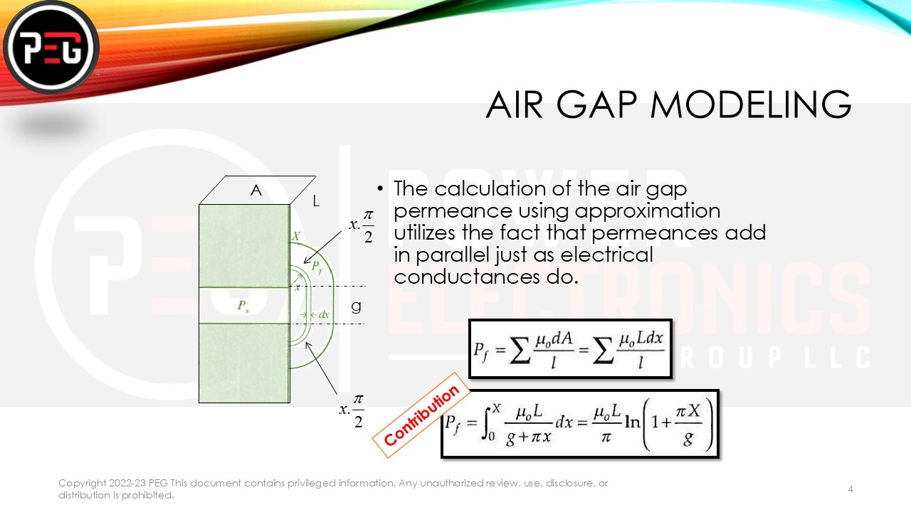
2.2 Air Gap Modeling
Permeance of an Air Gap measures the ease with which a magnetic flux can pass through an air gap in a magnetic circuit. It is the reciprocal of reluctance and is given by:
P=μ0A/g … Equation 1
where:
- P = Permeance (measured in Henries, H)
- μ0 = Permeability of free space (4π×10−7 H/m)
- A = Cross-sectional area of the air gap (m²)
- g = Length of the air gap (m)
Since air has a much lower permeability than ferromagnetic materials, the air gap introduces a significant reluctance in the magnetic circuit, which affects the overall magnetic performance of devices like transformers, inductors, and electric motors.
The air gap is critical in defining the motor’s magnetic field distribution. The air gap permeance is determined using the same equation as above:
Pg=μ0A/g … Equation 2
Where Pg is the air gap permeance, μ0 is the permeability of free space, A is the cross-sectional area, and g is the air gap length.
Here are the permeance values for different air gap lengths, assuming a cross-sectional area of 100 mm² (0.0001 m²):
- 1 mm air gap → 1.26×10⁻⁷H
- 2 mm air gap → 6.28×10⁻⁸ H
- 3 mm air gap → 4.19×10⁻⁸ H
As expected, the permeance decreases as the air gap increases, reducing the ease of magnetic flux flow.
What happens in a transformer with an air gap?
In Fig. 1, our primary focus is on the leakage flux around the air gap. If we define a leakage radius of x at the end of the air gap, the permeance for a differential segment dx can be calculated. The effective length of the flux path becomes g + πx, while the additional effective area to consider is L·dx. Pf represents the additional contribution to the total permeance due to the leakage flux.
Let us consider an example:
L = 12 mm
g = 2mm
A = 50 mm2
Pg = 3.14*10-05 H
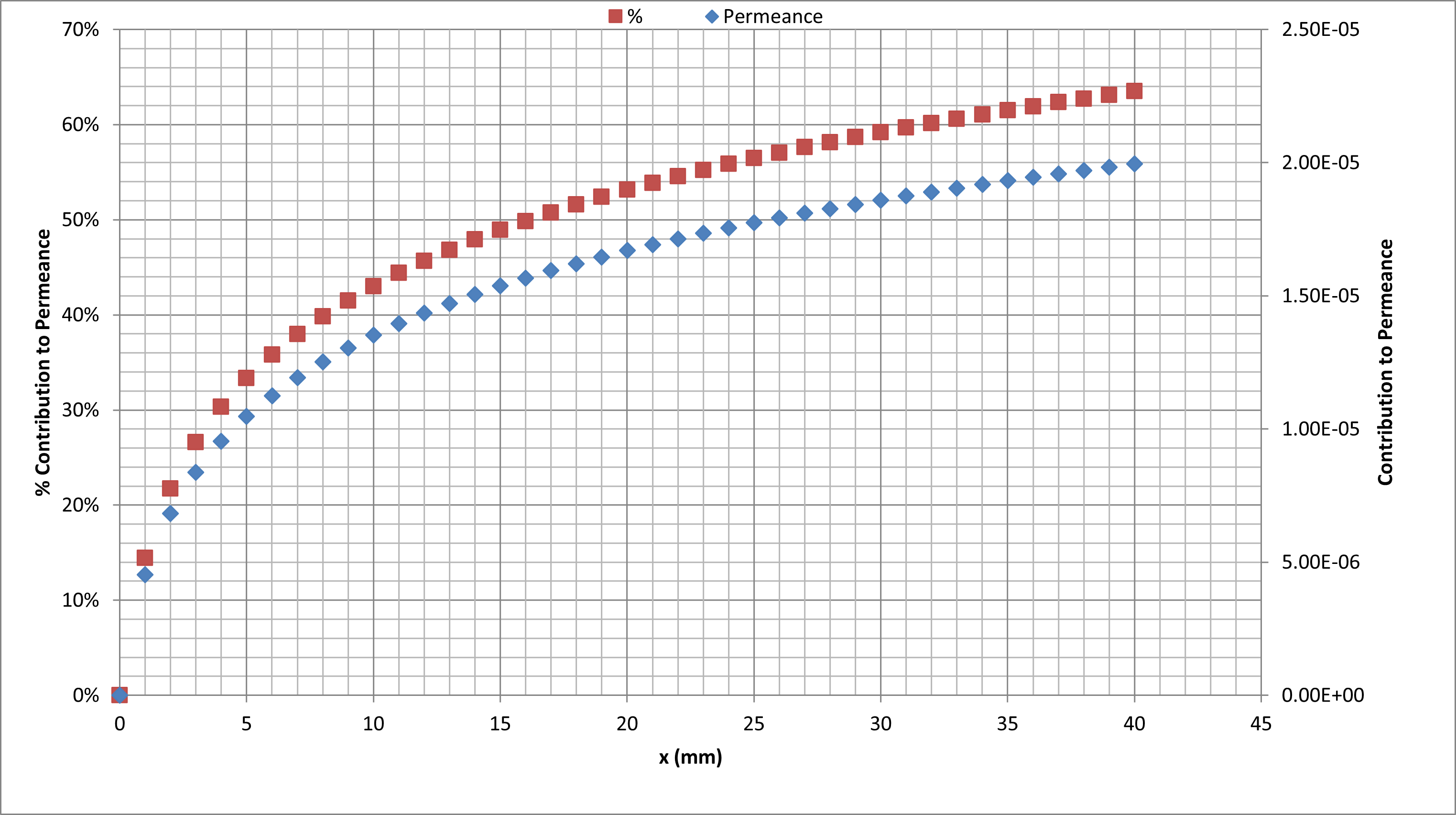
If we account for x in the leakage flux, we can use the above equation to determine Pf, representing the additional permeance the leakage flux contributed. The graph at the top (burgundy) shows the percentage contribution, and the graph at the bottom (sky blue) shows the actual value of the contribution. 50% contribution value is achieved at x= 15mm
Effects of Higher Permeance Due to Leakage Flux on Transformer Performance
When higher permeance is caused by leakage flux, it introduces several adverse effects on transformer performance:
- Reduced Magnetic Coupling
- Leakage flux does not effectively link both primary and secondary windings, leading to weaker electromagnetic coupling.
- This results in reduced energy transfer efficiency and increased losses.
- Increased Leakage Inductance
- Higher leakage permeance leads to increased leakage inductance, which opposes rapid changes in current.
- This can cause voltage spikes and transients, affecting the performance of power electronics circuits.
- Poor Voltage Regulation
- With increased leakage inductance, the output voltage drops significantly under load conditions.
- This makes the transformerless effective in applications requiring stable voltage output.
- Higher Core Losses & Heating
- More leakage flux results in additional eddy current and hysteresis losses, leading to excessive heating.
- Increased temperature can reduce the lifespan of the transformer and degrade insulation materials.
- Reduced Power Transfer Efficiency
- Since leakage flux does not contribute to power transfer, some magnetic energy is wasted.
- This decreases the overall efficiency of the transformer.
- Potential Electromagnetic Interference (EMI)
- Stray magnetic fields from leakage flux can interfere with nearby electronic components.
- This is especially problematic in high-frequency transformers used in power electronics.
Key takeaways:
- As we move further from the air gap, the contribution of differential permeances decreases.
- The exact values chosen are not that critical.
- As x increases beyond 10g, the total air gap permeance changes little.
- Higher permeance due to leakage flux negatively impacts transformer performance by increasing losses, reducing voltage regulation, and decreasing efficiency.
- To mitigate these effects, we need to control and optimize the leakage flux using better winding arrangements, magnetic shielding, or air gaps.
DISCUSSION: Discuss the implications of large air gaps concerning the motor design with thin stacks. How do you balance stack Height vs. air Gap? See the answer here.