Abstract
This paper presents a sensorless control technique for Permanent Magnet Synchronous Motors (PMSMs) using a BackEMF observer. Eliminating physical position sensors improves system reliability and reduces cost and complexity. The proposed method estimates the back electromotive force (BackEMF) by comparing actual and estimated motor current and processing the error through a Proportional-Integral (PI) controller. This technique aligns with conventional field-oriented control, where current is in phase with the BackEMF. The observer is modeled and simulated in LTSpice, and results show excellent agreement between actual and estimated BackEMF, validating the approach for real-time sensorless control applications.
Keywords
BackEMF Observer, PMSM, Sensorless Control, PI Controller, LTSpice Simulation, Motor Estimation, Electromechanical Systems, Field-Oriented Control
1. Introduction
Permanent Magnet Synchronous Motors (PMSMs) are widely used in electric vehicles, robotics, and industrial automation due to their high efficiency, power density, and precise control capabilities. Traditionally, position sensors like encoders or resolvers are employed for rotor position feedback, essential for proper commutation and torque control. However, these sensors increase the system cost and complexity and reduce reliability in harsh environments.
Sensorless control strategies, especially those based on BackEMF estimation, provide a compelling alternative. Among various sensorless techniques, the BackEMF observer is a straightforward and efficient approach that relies on the motor’s intrinsic electrical parameters to indirectly estimate rotor position and speed.
This paper focuses on designing and simulating a BackEMF observer for PMSMs. It outlines the theoretical framework, presents a control scheme based on PI error compensation, and demonstrates its effectiveness using LTSpice simulation results.
A BackEMF observer is an efficient way to implement sensorless control in Permanent Magnet Synchronous Motors.
Theoretical Background
Let us consider a single phase of a three-phase motor, as shown below.
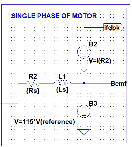
Figure 1: Single Phase of a Three-Phase Permanent Magnet Synchronous Motor
The equation for the single phase can be written as follows:

Equation 1
Where:
- Vin(t) = input voltage
- R= phase resistance
- L= phase inductance
- i(t) = phase current
- BEMF(t) = back electromotive force (BackEMF)

Equation 2
If we know Vin(t), R, L & i(t), we can calculate BackEMF. The following equation can estimate i(t).
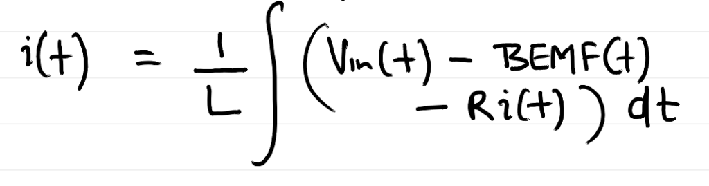
Equation 3
Now, we must remember that in a PMSM Motor, when we drive the motor without field weakening, we force the current to be in phase with the back EMF. Therefore, Motor current can represent the exact shape of the Back EMF. Knowing the above facts, let us look at a proposed scheme for implementing a BackEMF observer.
3. BackEMF Observer Scheme
The proposed BackEMF observer follows these steps:
- Measurement: Acquire the actual motor current (Ifdbk).
- Estimation: Compute the expected current using motor parameters and input voltage.
- Comparison: Calculate the error between measured and estimated currents.
- PI Control: Feed the mistake into a PI controller.
- BackEMF Estimation: Invert the PI controller output to estimate the BackEMF.
This control loop runs continuously, refining the BackEMF estimate in real-time, which can be used for further control decisions.
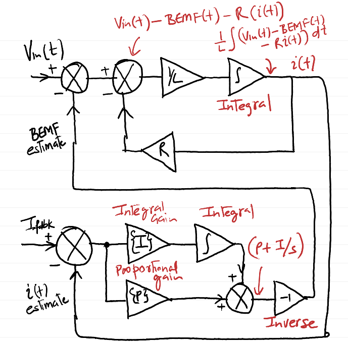
Figure 2 – Proposed BackEMF Observer Scheme
Ifdbk represents the actual measured current in the motor winding. Vin(t) is the applied voltage to the motor winding. We also estimate motor winding current using equation 3 above. That estimated current is compared against the measured current. The difference is run through a PI controller and inverted. The output of this block is our BackEMF estimate.
4. Implementing it using LTSpice
The observer model was implemented in LTSpice, and simulation blocks were constructed to emulate key motor and control dynamics:
- Unity Reference Block: Validates signal alignment.
- Voltage Control Block: Calculates input voltage from reference and feedback currents.
- Current Feedback and Measurement: Monitors winding current.
- Current Estimation Block: Simulates the expected current from known resistance and inductance.
- PI Estimator Block: Processes error and generates the BackEMF estimate.
- Complete Block Diagram: Integrates all components into one simulation system.
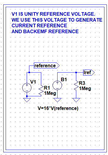
Figure 3 – Unity Reference implementation in LTSpice
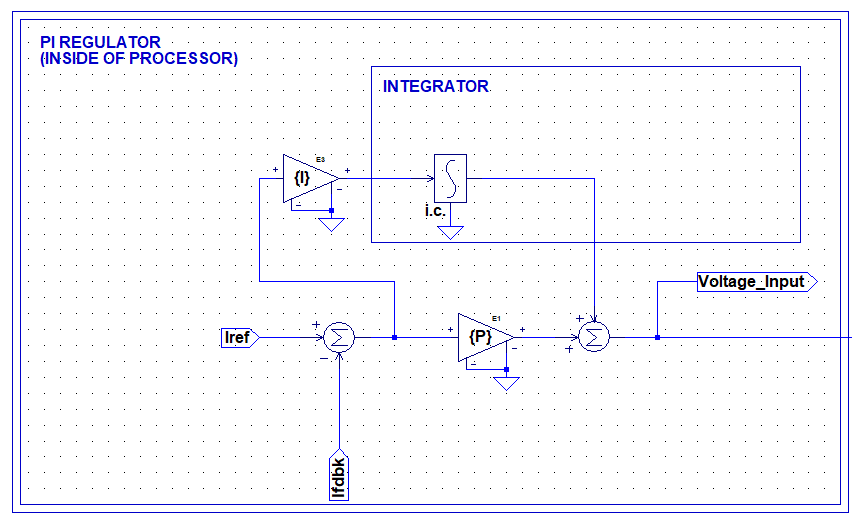
Figure 4 – Voltage to be applied to the motor winding is calculated based on Iref (Current Reference) and Ifdbk (Current Feedback).
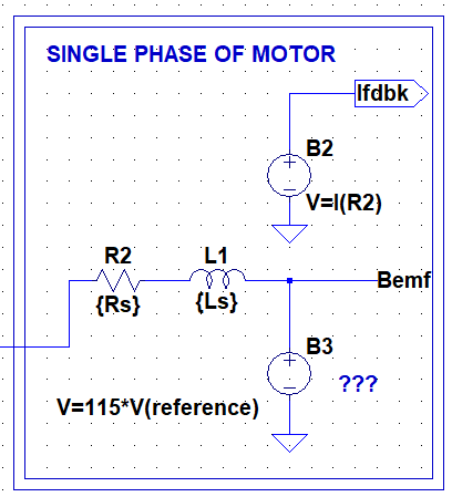
Figure 5 – The voltage input generated in Figure 4 is applied to the motor winding. Ifdbk is the measured current through the motor winding.
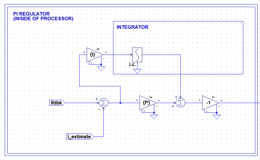
Figure 6—This is the block for estimating the Back EMF. Ifdbk is compared against an estimated current, run through a PI loop, and inverted to generate an estimate for the back EMF.
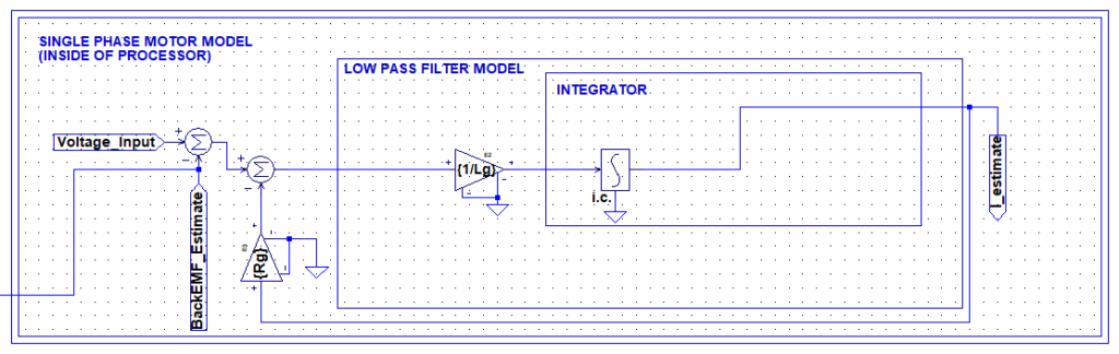
Figure 7 – This is the block for estimating the motor winding current through the system characteristics, i.e., resistance, inductance, etc.
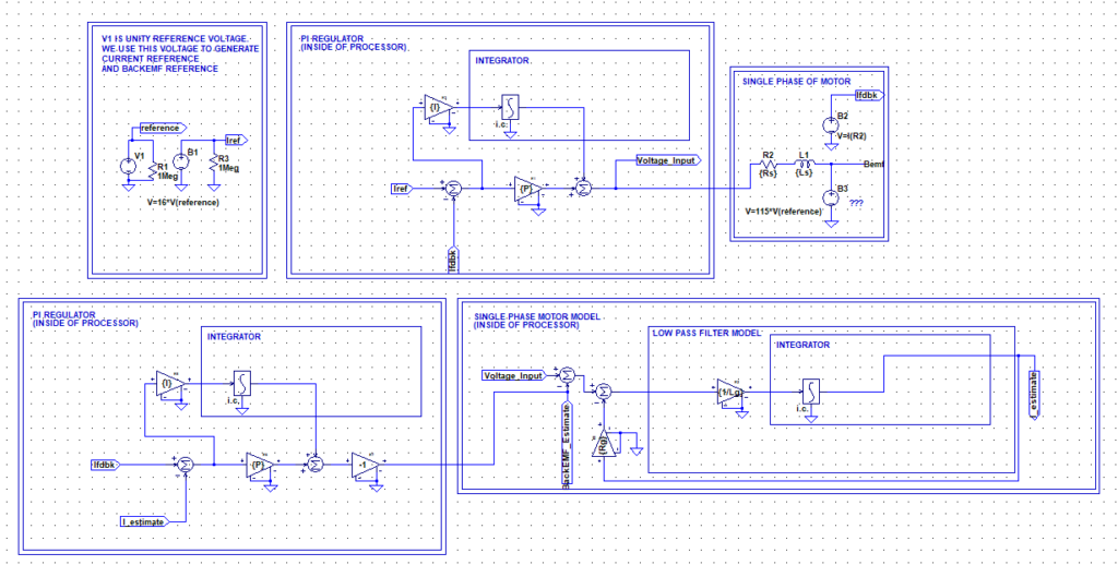
Figure 8 – Complete Block Diagram for the BackEMF Observer
5. Simulation Results
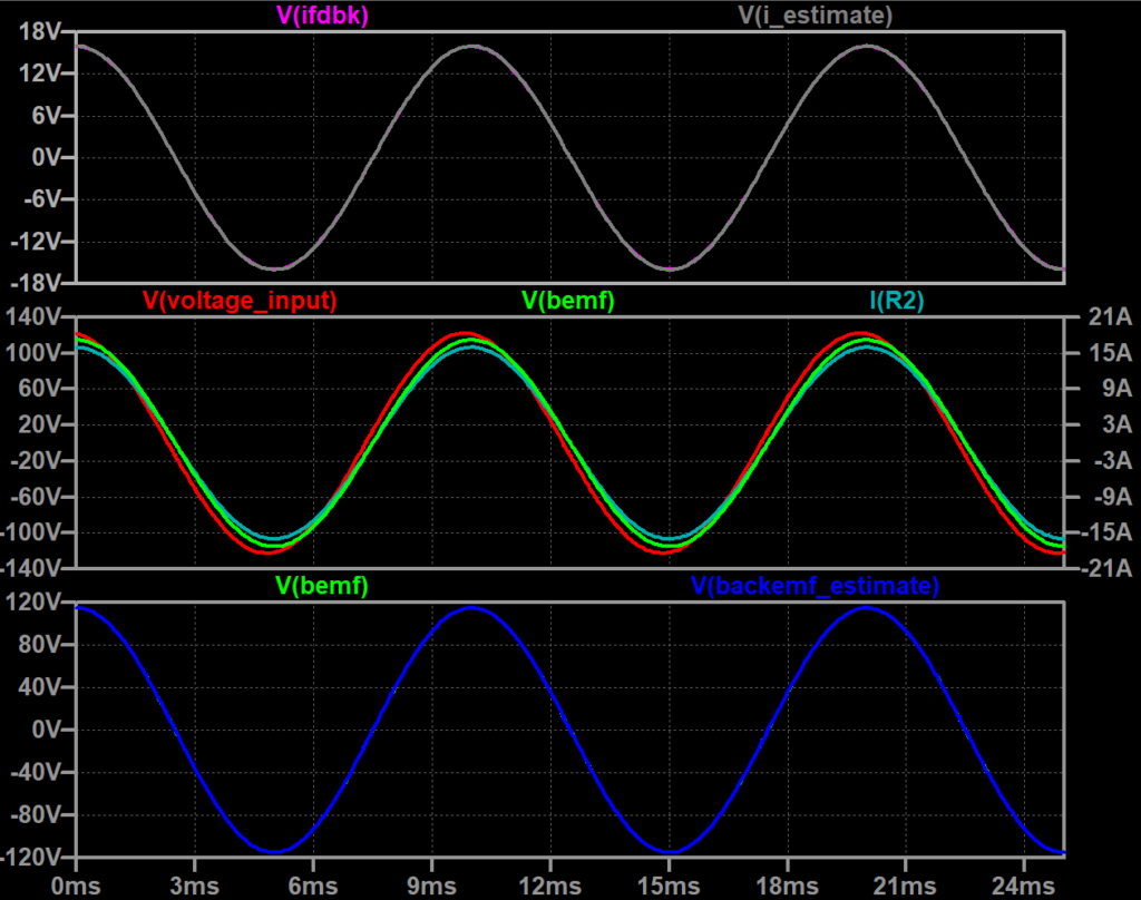
Figure 9—Current Feedback and Current Estimate are at the top. Voltage Input, backEMF, and Motor current are in the middle. BackEMF and estimated BackEMF are at the bottom.
The LTSpice simulation shows that the estimated BackEMF closely tracks the actual BackEMF across various operating conditions. This confirms that the observer can deliver reliable performance without needing position sensors. It demonstrates fast convergence, stability, and robustness to minor modeling inaccuracies.
The above video shows how well the actual BackEMF and estimated BackEMF match.
6. Conclusion
The BackEMF observer offers a viable and efficient technique for sensorless control in PMSMs. By leveraging current and voltage measurements and system parameters, it accurately estimates BackEMF in real time. The LTSpice simulation validates its performance and shows promise for embedded motor control applications, especially where cost and reliability are critical concerns.
Leave a Reply