


20
Oct, 2025
Workshop Videos and Slides Now Available
Rakesh K Dhawan, Power Electronics Group LLC
🎓 + Upcoming AI-Powered Motor Design Workshop I'm excited to share that our comprehensive brushless permanent magnet motor design workshop series is now available at the below links: Module 1: Fundamentals of Brushless Permanent Magnet Motor Design https://youtu.be/CFiz4UjcYZk?si=OhAULZkdu0QDUB-c Module 2: Motor and Magnetic Architectures https://youtu.be/6WTkHsLnso8?si=QgAVUoaOavvjv3i4 Module 3: Anal...
Read More
14
May, 2025
Finite Element Motor Design and Automation Using FEMM and MATLAB: A Practical Methodology for Motor Engineers
Rakesh K Dhawan, Power Electronics Group LLC
Rakesh Dhawan AbstractThe Finite Element Method Magnetics (FEMM) has emerged as a vital open-source tool for electromagnetic simulation, offering a cost-effective and reliable platform for electric motor analysis. This article presents a comprehensive overview of using FEMM for motor modeling and design validation, followed by its integration with MATLAB for automated simulation and data analysis. The methodology is demonstrated...
Read More
10
May, 2025
Design and Finite Element Analysis of Surface and Interior Permanent Magnet Motors for High-Efficiency Applications
Rakesh K Dhawan, Power Electronics Group LLC
Author:Rakesh Dhawan Abstract This paper presents a comprehensive design methodology and performance analysis of permanent magnet motor topologies using finite element analysis (FEA). Starting from defined customer specifications—including torque, speed, and thermal constraints—we investigate the impact of rotor-stator geometries and magnet configurations on electromagnetic torque, cogging torque, back-EMF waveform qualit...
Read More
10
May, 2025
Diagnostic Strategies and Protection Techniques for Electric Motor Drive Systems
Rakesh K Dhawan, Power Electronics Group LLC
Author:Rakesh Dhawan Abstract The complexity of modern electric motor drive systems, particularly involving Permanent Magnet Synchronous Motors (PMSMs) and Brushless DC (BLDC) motors, demands a robust approach to fault diagnosis and system protection. This paper investigates various failure modes, including winding overload, electromagnetic interference (EMI), torque ripple, cogging torque, and short-circuit conditions. F...
Read More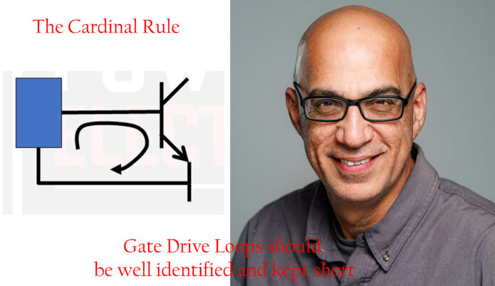
03
May, 2025
Minimizing Current Loops in High-Voltage Inverter PCB Layouts: Why It Matters
Rakesh K Dhawan, Power Electronics Group LLC
https://youtube.com/shorts/Ld-iq4DZjbI Designing a reliable and robust high-voltage inverter starts with a foundational principle in PCB layout—minimizing current loops. This is not just a best practice; it is essential to performance, safety, and electromagnetic compatibility (EMC). Just as we identify flux loops in motor design, we must identify and control current loops during the layout of an inverter. This becomes increa...
Read More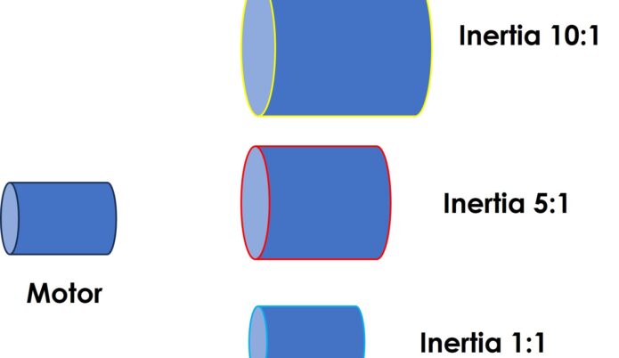
20
Apr, 2025
Inertia Matching - Rule of Thumb for Stability of Motion Systems
Rakesh K Dhawan, Power Electronics Group LLC
What Is Inertia Matching? Inertia is an object’s resistance to changes in motion (i.e., acceleration or deceleration).In a motor-drive system, you’re dealing with two key inertias: Motor inertia — the rotational inertia of the motor rotor Reflected load inertia — the inertia of the load as seen by the motor through the mechanical transmission (gearbox, pulley, etc.) Jload (reflected)=Jload/Gear Ratio2 Why...
Read More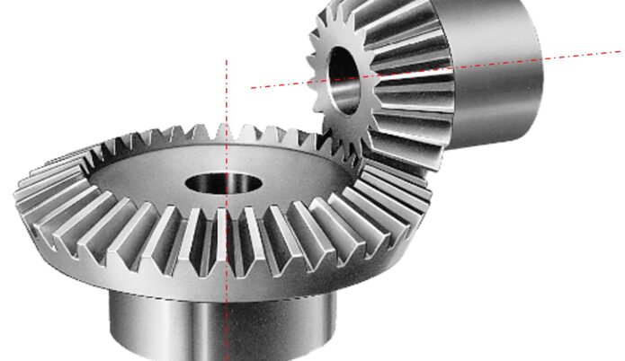
20
Apr, 2025
Motor Sizing: General Considerations with respect to Horizontal and Vertical Axes
Rakesh K Dhawan, Power Electronics Group LLC
When sizing a motor for an application, it is crucial to distinguish between horizontal and vertical motion axes, as each involves different load considerations and system dynamics. Here's how you should approach each: Before diving into horizontal vs. vertical, the core factors in motor sizing include: Load inertia (moment of inertia) Required torque and speed Acceleration and deceleration profiles Duty cycle and th...
Read More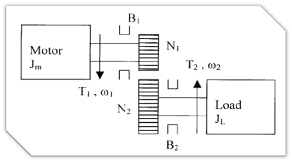
20
Apr, 2025
Transmitted Power and Peripheral Velocity
Rakesh K Dhawan, Power Electronics Group LLC
In rotational systems, peripheral velocity (also known as tangential or linear velocity at the rim of a rotating body) plays a key role in determining the power transmitted. Mathematically: P=F⋅v Where: P = Power F = Force (typically tangential) v = Peripheral velocity Since force is related to torque (T=F⋅r), we also get: P=T⋅ω=F⋅r⋅ω=F⋅v Thus, increasing peripheral velocity enables higher power transm...
Read More20
Apr, 2025
Understanding Power Transmission through Mechanical Couplings/Gearing Systems
Rakesh K Dhawan, Power Electronics Group LLC
In mechanical systems, transmitting power effectively from a prime mover (typically a motor) to a machine or between machines requires a crucial intermediary: the coupling. Couplings not only help tailor the power characteristics to suit specific application needs but also play a central role in ensuring reliability, efficiency, and precision in mechanical systems. The Role of Couplings in Power Transmission A prime mover, ...
Read More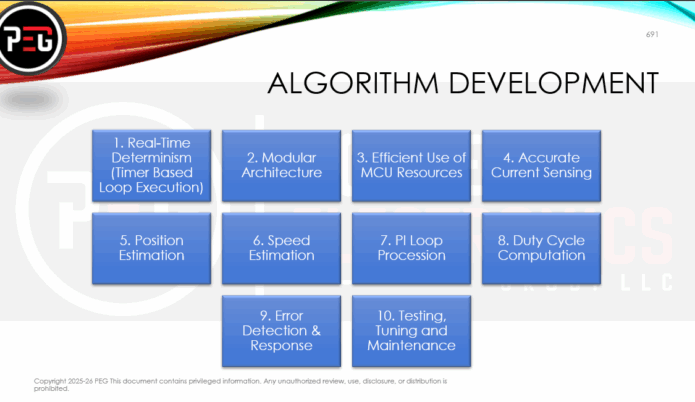
18
Apr, 2025
10 Keys to Efficient Motor Code Development
Rakesh K Dhawan, Power Electronics Group LLC
Whether you're building control software for a brushless DC motor (BLDC), PMSM, or induction machine, efficient motor code development is the cornerstone of robust, responsive, and safe performance. At the heart of real-time motor control lies a tight loop of functions executed every pulse-width modulation (PWM) cycle, typically in the range of 10 to 100 microseconds. Here's a comprehensive breakdown of the core principles of efficient...
Read More